This is a DIY project utilizing a nice 8 by 8 led kit I've soldered together, controlled with an ESP32DEVKITV1 board, coded using Arduino IDE
the DIY board offers external pins to be controlled from the outside, bought from aliexpress and soldered manually.
The following is the Schema of the board, provided kindly by the seller:
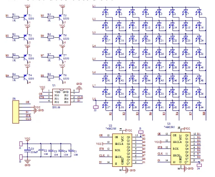
A few notes on the board:
- there are no permanent latching of the data, meaning that in order to see a constant pattern for a specific time, one must repeatedly send the pattern over and over again so it will create the illusion that the pattern is stable.
- there are two 8 bit led drivers, one for 8 rows and one for 8 columns. the first byte we send enables specific rows and the second byte we send will light up the leds of the rows that were enabled
- for example, we send 10000001 which will enable the 1st and the last rows, and then we send 00011000 which will light up the 4th and 5th leds of the first and the last rows.
- I could not identify the type of the single 8 pin chip, I'm not sure how does it plays in the mix.
- Note of the J4 point, I believe it is connected to a carry bit of some sort and it might allow us to concatenate multiple boards together.
There are variations for this project, one of them is using a 16x16 board and I recommand you to take a look at it.
16x16 led matrix with animations
8x8 led matrix with rotary encoder
- Download & install Arduino IDE
- Install the ESP32 Board in Arduino IDE: Open Arduino IDE.
- Go to File > Preferences.
- In the Additional Board Manager URLs field, add: https://dl.espressif.com/dl/package_esp32_index.json.
- Go to Tools > Board > Board Manager, Search for "esp32" and install the "esp32" platform.
- Select the ESP32 Board: Go to Tools > Board > esp32 > and select "ESP32 Dev Module".
The board runs a demo when provided with power only. The board has the following pins:
- OE: enable/disable pin
- IN: data-in pin. this data is shifted into the board bit by bit.
- STB: latch the data into the internal registers of the led drivers.
- CLK: clock pin used to time the data shifting from the IN pin.
- VCC, GND: power the board with either 3.3V or 5V.
The board is powered on its "Vin" & "GND" pins, and they can take input voltage from 4V to 12V.
When powered, the board provides a stable 3.3V on the its "3.3V" & "GND" pins that can power low current loads.
We select GPIO's 12,13,14 and 15 of the ESP32 board to the "OE", "IN", "STB", "CLK" of the led matrix.
- Connect external 5V power source to the "Vin" & "GND" pins of the ESP32 board.
- Connect pins from ESP32 board to the led matrix board pins:
- "GPIO12" to "OE"
- "GPIO13" to "IN"
- "GPIO14" to "STB"
- "GPIO15" to "CLK"
- "3.3V" & "GND" to "VCC" & "GND"
- ** it is possible to provide the matrix board with a separate 3.3V external voltage, to avoid the ESP32 board with the task to power it by itself. both ways will work
- Open the ".ino" code file in the IDE
- Disconnect the external power to the ESP32 board
- connect the ESP32 board to your host PC via USB and select the COM port
- Open windows Device manager and look under "ports" what is the port of the board.
- Go to Tools > Port > and select that port.
- The IDE should tell you that the board is connected at the bottom right corner of the app
- Hit the "Upload" button at the top left. the IDE will compile the program and if successful, it will attempt to upload the binaries to the ESP32 board. upon success it will show "100%" message at the log window.
- (optional) To prevent the host PC to power the boards, disconnect the USB cable and re-connect the external 5V power source to the ESP32 board.
At this point, the led matrix board should display and swap between 3 patterns in a 1 second interval.

- To add more patterns, simply add more data to the "patterns" variable.
- To make use of different GPIO's, make sure to change the definitions in the code, and it is recommended to select simple GPIO pins and not UART pins. do NOT use UART0 pins, you won't be able to flash new firmware if you do.
Pull requests are welcome. Make me smarted if you will ;)
Me?